Embedded module TQMa117xL
Deploying
To deploy the examples on the STKa117xL this is currently possible either via JTAG or Serial Downloader. Below you can choose which option is most suitable for you.
Preface
The following instructions describe how to prepare and generate the project and writing an image via flashloader with MCUXpresso Secure Provisioning tool.
| Tool | Version |
|---|---|
| GitHub Repository | MBa117xL.SW.MCU.BSP |
| VS-Code | Version 1.100.2 |
| MCUXpresso Secure Provisioning | Version 8.0 |
| MCUXpresso Config Tools | Version 15.1 |
Booting from flash
Writing the examples
STEP 1 - Rebuilding the image
DXIP_BOOT_HEADER_ENABLE=0
XIP_BOOT_HEADER_ENABLE controls whether the build embeds the FlexSPI configuration block, IVT, boot data, and optional DCD (1 = include, 0 = omit). Use 1 when loading via a debug probe and 0 for ISP/Secure Provisioning (which adds the header itself).
STEP 2 - Generating the dcd.bin
By default this file is located in examples/board in the project. Afterwards you need to select the Device Configuration tab from the menu icons. Select binary as output format in the DCD window and update the the code. The dcd.bin file should now be saved in the board folder.
STEP 3 - Building

Within the MCUXpresso Secure Provisioning tool main window select FlexSPI NOR – simplified to setup the NOR flash properly. Setup the NOR Flash in the Boot Memory Configuration window.
Afterwards the image for flashing can be built by clicking the Build image button.
STEP 3 - Flashing
Please ensure that the corresponding DIP Switches are configured for Serial Downloader mode.
Serial Downloader
S3
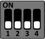
S4
S5
S6

Setup the target Hardware connection properly (USB (X2) or UART1 (X1)). If UART1 is used for flashing the corresponding COM Port and a baudrate of 115200 has to be configured.
Next, select the write image tab, start the flashloader and finally write the image.
After successfully writing the image, set the DIP Switches to internal boot and perform a powercycle.
Internal Boot
S3
S4
S5
S6

Preface
The aim of this guide is to debug a “Hello World” demo on the Cortex-M7 core of the TQMa117xL using VS code and a SEGGER J-Link.
Keep in mind that the paths specified in these instructions refer to the test system. Your paths may differ.
Prerequisites
Software/Extention Versions
If not already, please install the following Software and install the Serial Console VS-CODE extention listed in the tables below.
| Tool/Extention | Version |
|---|---|
| GitHub Repository | MBa117xL.SW.MCU.BSP |
| VS-Code | Version 1.88.1 |
| Segger J-Link for debugging | Version v8.83 |
ms-vscode.cmake-tools | CMake tools (from Microsoft): v1.16.3 |
marus25.cortex-debug | Cortex-Debug (from marus25): v1.12.0 |
ms-vscode.vscode-serial-monitor | Serial Monitor (from Microsoft): 0.13.1 |
Debugging
Debugging
Debugging
Set the DIP switches of the MBa117xL as follows to debug via JTAG:
DIP-Switch-Settings
S3
S4
S5
S6
- Connect your SEGGER J-Link to JTAG connector X39 on the MBa117xL.
- Connect a Micro USB cable to Serial Debug connector X1.
- Open your MBa117xL workspace in VS-Code and build a example.
- Select
Terminal > New Terminalin the top bar - Finaly debug your desired example following the istructions in the video below: