Table of Contents
EDID (Extended Display Identification Data)
Basic Information about EDID
EDID (Extended Display Identification Data) is a data structure between the graphics unit and the connected monitor. Via this the graphic unit receives the values of the display like timings, resolution, colors and further information about the used display. mostly the EDID data is stored as 128 byte large binary in an EEPROM which is then read via an interface like I2C.
Generate EDID data
EDID generators and editors are mostly used to create and customize EDID binaries. After the necessary values are collected from the display data sheet, they can be inserted into the tool. The edid generator creates the required binary from the entered data like resolution, standard timings and other values.
Prepare tool
Several EDID generators can be found on the internet, to name a few (in alphabetical order):
- Advantiv™ EDID Editor (Windows)
- AW EDID Editor (Windows, Mac OS)
- E-EDID Editor (Windows)
- wxEDID (Linux, Windows; available as source code only)
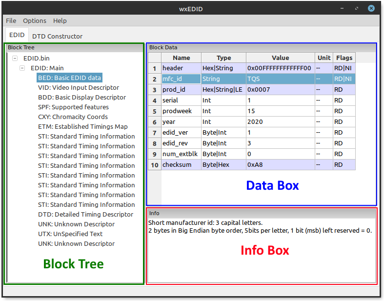
In this tutorial we will use the wxEDID editor (GPLv3) to explain the process.
Customize Data in Binary
- load the Bin file which should be edited: File > Open EDID Binary
- change the values using the data sheet for the display. Information about the currently selected value is displayed in the info box below.
- if the block DTD: Detailed Timing Descriptor is selected in the block tree, you can switch to the DTD Constructor tab at the top to set values like timing and resolution more easily and with graphical feedback regarding the display size.
- Once all changes have been entered into the tool, the binary file can be created: File > Save EDID Binary
Flash EDID Data
To change the EDID data on the populated PTN3460 chip, its firmware must be adapted. The Edid data is located at certain addresses in the firmware and therefore the old 128 bytes must be overwritten with the new created bytes.
Requirements
The firmware can be requested via the TQ-Support.
- Firmware.bin (PTN3460)
- new EDID Binary (128 Bytes)
- Flash-Tool “PTN3460 Flash-over-AUX” (Distribution only by NXP )
- Hex file manipulation program (eg. okteta)
- Latest graphics driver istalled
Edit Firmware Binary
 to change the EDID data in the chip, the created EDID data must be written into the firmware at the appropriate location:
- Open the PTN3460.bin and the created EDID.bin in a Hex Editor
- Search for the address of the Edid data in the firmware file, which should be replaced by the customized EDID data (use table EDID addresses below)
- Copy the 128 bytes from the created EDID file and overwrite the existing values at the correct address
- Make sure that the existing data is overwritten. The firmware binary must not contain more bytes than before!
- Save new Firmware.bin
Flash Firmware Binary
After creating the edited firmware binaries the file can be written to the LVDS bridge.
Before the tool is started, the required files must be located in the same folder as the tool.
Example (windows):

 <parent Folder>
    |--- FLASH.bin
    |--- PTN3460.bin (custom firmware binary)
    |--- AuxDLL.dll
    |--- PTN3460_FOA_App.exe
Start flash process:
- Boot the module on which the LVDS bridge should be flashed use an operating system which is supported by the NXP tool
- Start the Tool (PTN3460_FOA_App) and click on the button DISPLAY
- Select the Displaybridge in the dropdown-menu (DP0 on the most modules)
- Press the button Flash to start the flash process
As soon as the process has been completed without errors, the text “Programming complete” should appear in the info window.
Use new Resolution
- Reboot module and stop boot sequence in BIOS
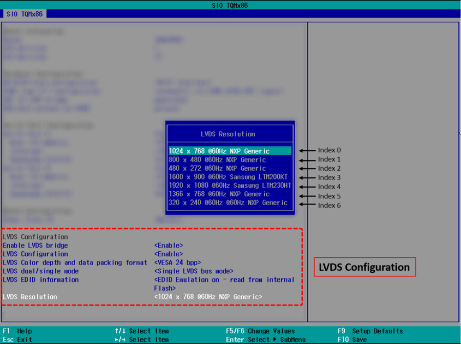
- From BIOS front page navigate to: Setup Utility → Advanced → SIO TQMx86
On older modules: Device Management → SIO TQMx86 - Enable Enable LVDS bridge and LVDS Configuration
- Set LVDS EDID information to EDID Emulation on
- Under LVDS Resolution select the entry that corresponds to the index selected in step “Edit firmware binary”
see this screenshot - Press F10 to save changes and then reboot the system