This is an old revision of the document!
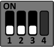
MBa28 DIP switch settings
Boot Device Selection (S4 & S5)
It is not possible to boot from SD card with the following Hardware combination TQMa28-A[C,D,E] Rev.02XX and MBa28 ≤ Rev.0105. please goto test
To select the desired boot medium set the DIP switches S4 and S5 accordingly. The following boot modes of the i.MX28 can be selected by the DIP switches S4 and S5 on the MBa28.
SD-Card
S4
S5
 S5-2: see User Manual, Table 69
eMMC
S4
S5
 S5-2: see User Manual, Table 69
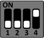
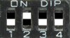
SD card
| S4 | S5 | |||||||||
|---|---|---|---|---|---|---|---|---|---|---|
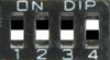 |  |
|||||||||
| DIP | 1 | 2 | 3 | 4 | 1 | 2 | 3 | 4 | ||
| ON | • | • | note | • | N/A | |||||
| OFF | • | • | • | |||||||
It is not possible to boot from SD card with the following Hardware combination TQMa28-A[C,D,E] Rev.02XX and MBa28 ≤ Rev.0105

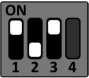
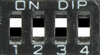
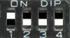
On-board eMMC
| S4 | S5 | |||||||||
|---|---|---|---|---|---|---|---|---|---|---|
 |  |
|||||||||
| DIP | 1 | 2 | 3 | 4 | 1 | 2 | 3 | 4 | ||
| ON | note | N/A | ||||||||
| OFF | • | • | • | • | • | • | ||||
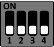
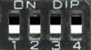
USB Recovery
| S4 | S5 | |||||||||
|---|---|---|---|---|---|---|---|---|---|---|
 |  |
|||||||||
| DIP | 1 | 2 | 3 | 4 | 1 | 2 | 3 | 4 | ||
| ON | • | • | note | N/A | ||||||
| OFF | • | • | • | • | ||||||
CAN configuration (S1)
DIP switch S1 is used to configure the CAN interfaces CAN1 and CAN2.

Termination
| DIP | OFF (default) | ON |
|---|---|---|
| S1-1 | CAN1 terminated (120Ω) | CAN1 not terminated |
| S1-2 | CAN2 terminated (120Ω) | CAN2 not terminated |
Slew rate
| DIP | OFF (default) | ON |
|---|---|---|
| S1-3 | CAN1 slew rate configuration disabled | CAN1 slew rate configurable by assembling R282 |
| S1-4 | CAN2 slew rate configuration disabled | CAN2 slew rate configurable by assembling R281 |
RS485 configuration (S3)
DIP switch S3 is used to configure the RS485 interface.

Debug
| DIP | OFF (default) | ON |
|---|---|---|
| S3-1 | No function | No function |
| S3-2 | DEBUG = GND | DEBUG = TQMa28 PU |
Termination
| DIP | OFF (default) | ON |
|---|---|---|
| S3-3 | RS485 RxD terminated (120Ω) | RS485 RxD not terminated |
| S3-4 | RS485 TxD terminated (120Ω) | RS485 TxD not terminated |
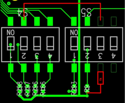
Workaround SD-Card Boot
Partlist
- hookup wire
- 1k resistor
TODO
- solder hookup wire from DIP S4-2 to DIP S5-3 (On is printed on the side of DIP switch)
- solder 1k resistor to Dip S5-3 (Number 3 is printed on the side of DIP switch)
- solder Connection between 1k resistor and the outer solder pad of R9
- set DIP S5-3 on