MBLS102xA DIP switch settings
Boot Device Selection (S3)
To select the desired boot medium set the DIP switches S3, S9 accordingly
SD-Card
S3
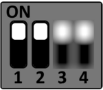
only for TQMLS102xA without eMMC
eMMC
S3
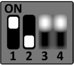
eMMC is a placement option on TQMLS102xA
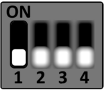
QSPI NOR
S3
S3-2 ON: TQMLS102xA without eMMC
S3-2 OFF: TQMLS102xA with eMMC
CPLD Function Selection (S9)
S9 DIP switch 1 + 2
| S9 | DIP 1 | DIP 2 |
|---|---|---|
| HDMI | ON | ON |
| LVDS | OFF | ON |
| UCC | ON | OFF |
| LVDS_RGBINV | OFF | OFF |
S9 DIP switch 3 + 4
| S9 | DIP 3 | DIP 4 |
|---|---|---|
| EC1 | ON | ON |
| CAN1 / CAN2 | OFF | ON |
| SAI1 / SAI2 | ON | OFF |
| Reserved | OFF | OFF |
The settings of DIP S9 has to match the TQMLS102xA BSP RCW configuration.
CPLD mux mode #1 EC1_HDMI matches the default RCW configuration of the TQMLS102xA BSP.
If DIP S9 is not set to one of the CPLD mux modes #1 - #12, the CPLD firmware selects mux mode #1.
If DIP S9 is not set to one of the CPLD mux modes #1 - #12, the CPLD firmware selects mux mode #1.
| Function | S9-1 | S9-2 | S9-3 | S9-4 |
|---|---|---|---|---|
| #1 EC1 + HDMI | ON | ON | ON | ON |
| #2 EC1 + LVDS | OFF | ON | ON | ON |
| #3 EC1 + UCC | ON | OFF | ON | ON |
| #4 EC1 + LVDS_RGBINV | OFF | OFF | ON | ON |
| #5 CAN + HDMI | ON | ON | OFF | ON |
| #6 CAN + LVDS | OFF | ON | OFF | ON |
| #7 CAN + UCC | ON | OFF | OFF | ON |
| #8 CAN + LVDS_RGBINV | OFF | OFF | OFF | ON |
| #9 SAI + HDMI | ON | ON | ON | OFF |
| #10 SAI + LVDS | OFF | ON | ON | OFF |
| #11 SAI + UCC | ON | OFF | ON | OFF |
| #12 SAI + LVDS_RGBINV | OFF | OFF | ON | OFF |
| #13 - #16 reserved | / | / | OFF | OFF |
Functional DIP Switches
DIP-Switch settings for CAN and RS485.
CAN configuration (S2)
DIP switch S2 is used to configure the CAN interfaces CAN1 and CAN2.
| DIP | OFF (default) | ON |
|---|---|---|
| S2-1 | CAN0 not terminated | CAN0 interface terminated (120Ω) |
| S2-2 | CAN1 not terminated | CAN1 interface terminated (120Ω) |
RS485 configuration (S1)
DIP switch S1 is used to configure the RS485 interface.
| DIP | OFF (default) | ON |
|---|---|---|
| S1-1 | RS485 RxD not terminated | RS485 RxD terminated (120Ω) |
| S1-2 | RS485 TxD not terminated | RS485 TxD terminated (120Ω) |