Embedded module TQMxE39C2 Documentation
Take screenshot from BIOS or UEFI shell
Take a screenshot from the BIOS
- Connect a USB stick (FAT32 formatted) to the mainboard
- Boot the system into the BIOS menu and move to the desired BIOS screen
- Press <F11> to take a screenshot of the actual screen
- Select the desired storage device in the pop-up window and press <Enter>
Take a screenshot from the UEFI shell
- Connect a USB stick (FAT32 formatted) to the mainboard
- Boot the System into the UEFI shell
- Press <F11> to take a screenshot of the actual screen
- Select the desired storage device in the pop-up window and press <Enter>
BIOS/UEFI Configuration
Activate eMMC
To activate or deactivate eMMC Support apply the following settings.
- Boot the system into the BIOS menu
- Set up 'SCS/SCC Configuration' option in the BIOS Menu accordingly:
Setup Utility > Advanced > South Cluster Configuration > SCC Configuration
- Press <F10> to save the settings and reboot the system
Activate Console Redirection
To activate Console Recirection in the BIOS via the serial port in addition to the display output on the Starterkit apply the following steps.
It can be useful for BIOS remote control tasks.
On Starterkit
- Connect a null modem cable to the desired serial interface (e.g. SER0)
- Boot the system into the BIOS menu
- Enable 'Console Redirection' option in the BIOS Menu and the corresponding serial port (e.g. COMA)
Setup Utility > Advanced > Console Redirection > Enabled
- Press <F10> to save the settings and reboot the system
On Host PC
- Connect the null modem cable to an available serial port
- Run your favorite terminal emulator on your Host PC (we recommend TeraTerm Pro)
- Configure the serial port according to the table below:
| Bautrate: | 115200 |
|---|---|
| Data bits: | 8 |
| Parity: | none |
| Stop bits: | 1 |
| Handshake : | XON/XOFF |
⇒ Reboot the Starterkit and use the terminal emulator to set up the BIOS
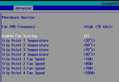
Hardware Monitor Fan Scaling
With 'Fan Scaling' option it is possible to control the system temperature at a certain load of the system by setting up the fan speed at certain trip points.
To create a custom 'Fan Scaling' plan apply the following steps in the BIOS setup.
- Boot the system into the BIOS menu
- Enable 'Fan Scaling' option and set it up according to your needs
Setup Utility > Advanced > SIO Hardware Monitor Nuvoton NCT7802Y > Enable Fan Scaling
- Press <F10> to save the settings and reboot the system
Activate/Deactivate CPU cores
To activate or deactivate CPU cores apply the following settings.
- Boot the system into the BIOS menu
- Set up 'CPU Configuration' option in the BIOS Menu accordingly:
Setup Utility > Power > CPU Configuration > Core 0-4 > Enable/Disable
- Press <F10> to save the settings and reboot the system
State after G3
With 'State after G3' option you can specify the behaviour of the system after power is supplied.
Configuring 'State after G3:
- Boot the system into the BIOS menu
- Set up 'State after G3' option in the BIOS Menu accordingly:
| State | Definition |
|---|---|
| S0 | System starts up directly after power is supplied |
| S5 | System is held in power-off state until power button is pressed |
Setup Utility > Advanced > South Cluster Configuration > Miscellaneous Configuration > State After G3
- Press <F10> to save the settings and reboot the system
Enable LVDS Display Output
Enable the LVDS interface
1. Check if your module variant support LVDS:
BIOS Front Page > Device Manager > SIO TQmx86 > eDP to LVDS bridge = populated
2. Enable the LVDS inteface in SIO TQMx86:
BIOS Front Page > Device Manager > SIO TQmx86 > LVDS Configuration = <Enable>
3. Enable eDP to use the LVDS Interface (eDP-to-LVDS Bridge is used):
Setup Utility > Advanced (Tab) > Uncore Configuration > VBT Hook Configuration > LFP 1 Configuration = <eDP>
4. Press the changes by pressing the key F10 on your keybaord
Configure the LVDS interface
The LVDS interface settings can be found on the following BIOS page:
BIOS Front Page > Device Manager > SIO TQmx86
| Setting | Description |
|---|---|
| LVDS Color depth and data packing format | Change the color depth and data packing format acording to your display: > VESA 24 bpp > JEIDA 24 bpp > VESA and JEIDA 18 bpp |
| LVDS dual/single mode | Select your LVDS bus mode: > Single > dual |
| LVDS EDID information | EDID information includes display specific values like timing and resolution. They are normally located in an I2C EEPROM on the display or baseboard. The LVDS bridge offers you to emulate a set of different display resolutions without the need of an EEPROM. Turn EDID emulation on to use one of the display presets |
More information can be found under Custom LVDS resolution (EDID).