Starterkit Quicksteps
The Starterkit STKa57xx consisting of the TQMa57xx module and MBa57xx mainboard is intended as evaluation platform for the TQMa57xx. To bring up the board a comprehensive set of accessories is supplied with the kit. The STKa57xx is delivered preconfigured to boot the latest released Linux BSP revision at the time of delivery, so only the Host Computer has to be set up properly to bring the STKa57xx up. This page guides through the first steps with the STKa57xx Starterkit.
Setup Host Computer
Serial Driver
The TQMa57xx debug UART is connected via a RS232 Transceiver to X4 on the MBa57xx. An RS232 cable is part of the STKa57xx accessory set.
Linux
The FTDI driver is maintained in the Linux mainline kernel, the configuration options below must be activated in the Linux kernel configuration to operate the USB-to-Serial converter
- CONFIG_USB_SERIAL
- CONFIG_USB_SERIAL_FTDI_SIO
Windows
The driver can be downloaded from the FTDI website:
https://ftdichip.com/drivers/vcp-drivers/
An installation guide can be found at the following link:
https://ftdichip.com/document/installation-guides/
Terminal Emulator
Linux
Minicom
Minicom is a command line based serial terminal for serial communication with hardware like our starterkits.
Install Minicom using APT(Debian/Ubuntu)
$ sudo apt install minicom
In order for the terminal to work properly with full rights you need to add your user to the dialout group:
$ sudo usermod -a -G dialout $USER
Connect Starterkit to Host
To determine the serial device name under linux you can use dmesg. Just run the command below and then plug in the starter kit to see the new detected interface names:
$ dmesg -w
Once the interface name is clear you can abort dmesg with ctrl + c.
Now you can start minicom via the command line interface:
$ minicom -D /dev/ttySx
Configure minicom
The serial configuration should be correct by default. However, hardware flow control must be disabled for some starter kits, otherwise the communication works only in one direction.
- Press CTRL + A, then press O to open the configuration menu
- Go to Serial port setup
- Press F to change Hardware Flow Control to No
- Hit Return key
- Select Save setup as dfl to save this configuration as default
- Press ESC to exit the menu
Now you should be able to communicate with the starter kit

Windows
TeraTerm
TeraTerm is an open source terminal emulator for windows. it can be downloaded here.
Configure TeraTerm
- Download and install TeraTerm
- Start TeraTerm and open the Serial Port Settings
- Select your serial port and configure it with the values defined in the chapter Serial Configuration
- After passing the values click on the button New Setting
Now TeraTerm should be ready for use with our starter kits.

Host PC Serial Port Configuration
The serial port which connects the STKa57xx to the Host PC must be configured as follows:
| Baud rate: | 115200 |
|---|---|
| Data bits: | 8 |
| Parity: | none |
| Stop bits: | 1 |
| Handshake: | XON/XOFF |
Connecting the Starterkit to the Development Host
Please follow the quick start guide delivered with the kit, or open it from the following link: Quick start guide
Linux
BSP Login Credentials
As soon as logging in on the Linux shell for the first time, the question about the login credential comes up.
By default the user root is used to log into the Linux shell, no password is set for user root.
tqmaxx-mbaxx login: root
Testing Interfaces on STKa57xx
To get familiar with the interfaces of the STKa57xx we recommend to work through the interface tutorials first.
Building the BSP
The Board Support Packages provided by TQ may not contain all software packages to evaluate the STKa57xx, therefore TQ provides some guides how to build the BSP and customize it for your needs:
In addition to the BSP documentation, the Yocto SDK build and Eclipse IDE setup for the STKa57xx is also documented.
Setup Starterkit for different boot sources
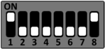
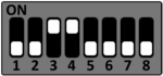
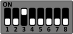
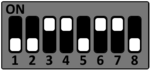
The STKa57xx can be setup to boot from different sources. Please see the DIP switch settings below to change the boot source.
To select the desired boot medium set the DIP switches S1 and S2 accordingly.
The following boot modes of the AM57XX can be selected by the DIP switches S1 and S2 on the MBa57xx.
SD-Card
S1
S2
eMMC
S1
S2
QSPI NOR
S1
S2
Functional DIP Switches
DIP-Switch settings for interfaces like JTAG, RS485 and CAN.
CAN1 (X5)
DIP switch S3 is used to configure the CAN interface CAN1.
Both switches must be set to ON or OFF otherwise the CAN Bus has an improper termination.
| DIP | S3-1 & S3-2 |
|---|---|
| ON | CAN Bus not terminated |
| OFF (default) | CAN Bus terminated (120Ω) |
CAN2 (X6)
DIP switch S7 is used to configure the CAN interface CAN2.
Both switches must be set to ON or OFF otherwise the CAN Bus has an improper termination.
| DIP | S7-1 & S7-2 |
|---|---|
| ON | CAN Bus not terminated |
| OFF (default) | CAN Bus terminated (120Ω) |
RS485 configuration (S5)
DIP switch S5 is used to configure the RS485 interface.
| DIP | S5-1 | S5-2 |
|---|---|---|
| ON | RS485 TxD terminated (120Ω) | RS485 RxD terminated (120Ω) |
| OFF (default) | RS485 TxD not terminated | RS485 RxD not terminated |
JTAG configuration (S13)
DIP switch S13 is used to configure the JTAG interface.
| DIP | S13 |
|---|---|
| ON | JTAG via connector X11 |
| OFF | JTAG via Micro-USB (x10) |