Embedded module TQMa8MxNL - YOCTO Linux BSP documentation
Starterkit Interfaces and Functions
Audio
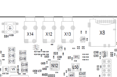
Audio Connector Overview
| Connector | Function |
|---|---|
| X12 | Microphone |
| X14 | Line In |
| X13 | Line Out |
Audio Connector Location

Play Audio on MBa8Mx
A simple test sound can be played with the commandline tool speaker-test.
Headphones or active speakers have to be connected to X13 on MBa8Mx.
speaker-test --channels 2 --test wav -D sysdefault:CARD=tqtlv320aic32x
You can also play your own audio files using aplay
aplay <file>
e.g.
aplay test.wav
Record Audio via Line-In on MBa8Mx
arecord -f cd test.wav
amixer or alsamixer
“}}
Buttons
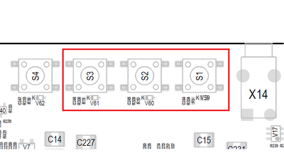
There are three GPIO buttons on the MBa8Mx. They are bound to the gpio-keys driver, and can be tested with the evtest tool.
GPIO Button Overview
| Reference | Button |
|---|
GPIO Button Location

The buttons are available in the sysfs via the device and can be tested with the evtest tool.
“|button_device=”/dev/input/event0”|button_test=“evtest /dev/input/event0”}}
CPU
The STKa8MxNL supports DVFS (dynamic voltage and frequency scaling, by default the governor ondemand is set.
Governors are power schemes for the CPU. Only one may be active at a time.
| Governor | description |
|---|---|
| performance | Run the CPU at the maximum frequency. |
| powersave | Run the CPU at the minimum frequency. |
| userspace | Run the CPU at user specified frequencies. |
| ondemand | Scales the frequency dynamically according to current load. Jumps to the highest frequency and then possibly back off as the idle time increases. |
| conservative | Scales the frequency dynamically according to current load. Scales the frequency more gradually than ondemand. |
| schedutil | Scheduler-driven CPU frequency selection |
You can change the actual governor with the following command:
cpufreq-set -g <governor>
(e.g. cpufreq-set -g performance)
Disable CPU Core temporarily
At runtime it is possible to disable multiple CPU cores via the Linux sysfs. On a system that has four CPU cores, the maximum of three cores can be disabled.
To disable the a CPU core value 0 must be written to the CPU core specific file /sys/devices/system/cpu/cpu<N>/online where <N> is the number of the Core, the counting starts at zero.
e.g. disable CPU core 4:
echo 0 > /sys/devices/system/cpu/cpu3/online
To check which CPU core(s) are currently enabled the following command can be used:
grep "processor" /proc/cpuinfo
The CPU core can be enabled again by writing the value 1 to /sys/devices/system/cpu/cpu<N>/online.
e.g. enable CPU core 4:
echo 1 > /sys/devices/system/cpu/cpu3/online
Set ammount of CPU Cores permanently
It is possible to limit the maximium amount of cores with the the maxcpus= parameter in the kernel command line. To add the new parameter a new U-boot variable addcpu has to be created.
setenv addcpu maxcpus=${cpu_num}
The amount of cores is set by the cpu_num variable, for example if cpu num is set to 2 only two cores will be started.
setenv cpu_num 2
Ethernet
The STKa8MxNL Starterkit provides one Gigabit Ethernet interfaces.
U-Boot
The IP configuration can be done statically or by a DHCP server in the network.
IP configuration via DHCP
For a configuration via a DHCP server, use the dhcp command in U-Boot.
Static IP configuration For a static IP configuration the following, U-Boot environment variables must be set:
setenv ipaddr <ipaddr>
(e.g.: setenv ipaddr 192.168.100.111)
setenv netmask <netmask>
(e.g.: setenv netmask 255.255.255.0)
Linux
The Ethernet interface is activated and configured by systemd-network. The configuration file for the interface is located in /lib/systemd/network/ these configuration file can be altered to customize the default interface configuration. A documentation of the configuration files can be found here.
| eth0 | 10-eth0.network |
For a temporary static configuration the ip command can be used, below some useful ip commands are listed:
Activate a specific interface
e.g. eth0
ip link set eth0 up
Disable a specific interace
e.g. eth0
ip link set eth0 down
Show ip address for a specific interface
e.g. eth0
ip addr show eth0
Show statistic for a specific interface
e.g. eth0
ip -s link show eth0
Set ip address for a specific interface
e.g. eth0
ip addr add 192.168.1.100/24 dev eth0
Show statistic of all interfaces
ip -s link
Set default gateway for a specific interfaces
e.g. set gateway ip 192.168.1.1 for eth0
ip route add default via 192.168.1.1 dev eth0
If a DHCP server is available in the network environment the ip configuration can be received from it. To do so execute the udhcpc command, by default eth0 is used.
To configure another interface via dhcp the parameter -i followed by the interface name e.g. eth1 must be given.
e.g. eth1
udhcpc -i eth1
GPU
Run GPU benchmark with connected display and loaded device tree in fullscreen mode:
glmark2-es2-wayland --fullscreen
I2C
An overview of the onboard i2c devices is available here
U-Boot
Select i2c bus device
i2c dev 0
Show all devices connected to the i2c bus currently selected:
i2c probe
Linux
Detect all devices connected to a i2c bus:
i2cdetect 2
LVDS
TQ offers an optional LVDS Display kit for the STKa8MxNL. Each Display can be used on its own by using the corresponding device tree. To allow reusage, the support for each display is separated in a dtsi fragment.
The DIP Switch S9-4 must be OFF.
To bring up the display the U-Boot environment has to be adapted accordingly.
- Interrupt boot process in U-boot
- Set U-Boot environment variable fdtfile with the command
setenv fdtfile imx8mn-mba8mx-lcdif-lvds-tm070jvhg33.dtb - Save the envrionment by executing the
saveenvcommand
MIPI-CSI
Hardware Setup
Instructions for setting up and connecting the camera can be found in the Camera QuickStartGuide:
MIPI-CSI Quick start guide
Software Setup
The following software example displays the live image of the camera on the HDMI interface of the starter kit.
To view the live image, an HDMI monitor must be connected.
Camera imx327 (color)
1. Start the Kit and stop in Uboot
2. Select the appropriate Devicetree for the use of the Camera:
setenv fdt_file imx8mp-mba8mpxl-hdmi-imx327.dtb
3. Save the environment to automatically load the selected devicetree for the next launches:
saveenv
4. Boot the kernel:
boot
5. When linux is started, login and configure the cam:
yavta -f SRGGB10 -s 1280x720 /dev/video0
6. run the following command to see the camera output on HDMI:
gst-launch-1.0 v4l2src device=/dev/video0 force-aspect-ratio=false ! video/x-bayer,format=rggb,bpp=10,width=1280,height=720,framerate=25/1 ! bayer2rgbneon show-fps=t reduce-bpp=t ! autovideoconvert ! autovideosink sync=false
Camera ov9281 (monochrome)
1. Start the Kit and stop in Uboot
2. Select the appropriate Devicetree for the use of the Camera:
setenv fdt_file imx8mp-mba8mpxl-hdmi-ov9281.dtb
3. Save the environment to automatically load the selected devicetree for the next launches:
saveenv
4. Boot the kernel:
boot
5. When linux is started, login and configure the cam:
yavta -f Y8 -s 1280x800 -c20 /dev/video0
6. Run the following command to see the camera output on HDMI:
gst-launch-1.0 v4l2src device=/dev/video0 ! videoconvert ! autovideosink -v sync=false
RTC
To set the hardware clock to the actual time and date use the following commands:
date -s [YYYY.]MM.DD-hh:mm[:ss]
hwclock -w
SPI
The MBa8Mx has two SPI interfaces. They can be found on the extension headers and can be tested with a loopback test.
SPI Overview
| Interface | linux filesystem |
|---|
Loopback Test SPI Interface
For the loopback test you need a bridge between SPI_MOSI and SPI_MISO:
echo -n -e "\x01\x0F" | spi-pipe -d <spi interface> -s 10000000 | hexdump
(e.g. echo -n -e "\x01\x0F" | spi-pipe -d /dev/spidev1.0 -s 10000000 | hexdump)
SSH Connection
The file /etc/ssh/sshd_config is used to configure the SSH service. To be able to login with a password as user root change the following lines in the Authentication section
PermitRootLogin prohibit-password
to
PermitRootLogin yes
and
#PasswordAuthentication yes
to
PasswordAuthentication yes
After altering the SSH configuration, the SSH service must be restarted to apply the new configuration:
systemctl restart sshd.socket
To setup a password for a user,
execute the command passwd <username>, e.g. passwd root for the default user root, and set your password. Afterwards execute the login command to login the user with the new password.
Temperature Sensors
@temp_description@ @temp_sensors@
USB
With lsusb you can see all connected usb devices. To mount a partition of an usb stick you can excute mount /dev/<partition> <mount dir> (e.g. mount /dev/sdb1 /mnt). This will mount the first partition of sdb to /mnt. To unmount the device execute umount <mount dir> (e.g. umount /mnt).
User LED
The STKa8MxNL has two user controllable LEDs, the behavior of these LEDs can be selected by several triggers.
User LED Overview
| Reference | LED name | color | linux filesystem |
|---|
User LED Location
“{{ :intern:arm:tqma8mxnl:linux:yocto:mba8mx_user_led.png?nolink&400 |
The user LED's are located in .
To change the behaviour a specific LED, the value in the file trigger must be overwritten.
The following values are valid:
For example set the trigger of to heartbeat
echo heartbeat >
“|userled_location=”/sys/devices/platform/gpio-leds/leds/“|led_example=“led1”|userled_example=”/sys/class/leds/led1/trigger“}}