Embedded module TQMLS1028A - YOCTO Linux BSP documentation
Starterkit Interfaces and Functions
Buttons
There are two GPIO buttons on the MBL1028A. They are bound to the gpio-keys driver, and can be tested with the evtest tool.
GPIO Button Overview
| Reference | Button |
|---|---|
| S4 | Button 0 |
| S5 | Button 1 |
GPIO Button Location
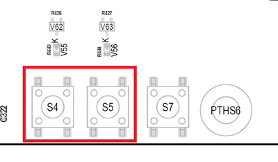
The buttons are available in the sysfs via the device /dev/input/event0 and can be tested with the evtest tool.
evtest /dev/input/event0
CAN
The STKLS1028A provides the CAN Interfaces can0 and can1.
CAN configuration
DIP switch S1 is used to configure the CAN interfaces CAN0 and CAN1.
| Function | S1-1 | S1-2 |
|---|---|---|
| CAN-Bus not terminated | OFF | OFF |
| not defined (illegal state) | OFF | ON |
| not defined (illegal state) | ON | OFF |
| CAN-Bus terminated with 120 Ohm | ON | ON |
CAN Loopback
“{{ :en:layerscape:tqmls1028a:linux:yocto:tqmls1028a_can_loopback.png?nolink&400 |
Loopback Test CAN Interface
CAN0 -> CAN1
candump can0&
cansend can1 5A1#11.2233.44556677.88
CAN1 -> CAN0
candump can1&
cansend can0 5A1#11.2233.44556677.88
Ethernet
The STKLS1028A provides one 4 Port TSN Gbit Ethernet Switch and two 10/100/1000 Ethernet Interfaces.
Configure the ethernet switch in bridge mode
The TSN switch of the STKLS1028A is not configured by default. The master interface eno2 is enabled by default, so it is not necessary to bring it up manually.
Single port configuration
Every single switch port acts as a configurable Ethernet port
# Configure each single switch interface and bring it up.

$ ip addr add 192.168.1.2 dev swp0 && ip link set swp0 up
$ ip addr add 192.168.1.3 dev swp1 && ip link set swp1 up
$ ip addr add 192.168.1.4 dev swp2 && ip link set swp2 up
$ ip addr add 192.168.1.5 dev swp3 && ip link set swp3 up
Bridge configuration
Every switch port is part of one configurable Ethernet bridge.
# Create a bridge device in this example it is called switch

$ ip link add name switch type bridge

# Bring up the bridge device

$ ip link set switch up

# Add the interfaces to the bridge device switch and bring them up.

$ ip link set swp0 master switch && ip link set swp0 up
$ ip link set swp1 master switch && ip link set swp1 up
$ ip link set swp2 master switch && ip link set swp2 up
$ ip link set swp3 master switch && ip link set swp3 up

# Configure bridge device

$ ip addr add 192.168.1.2 dev switch
U-Boot
In U-Boot enetc-1 is configured as default interface. The IP configuration can be done statically or by a DHCP server in the network.
IP configuration via DHCP
For a configuration via a DHCP server, use the dhcp command in U-Boot.
Static IP configuration For a static IP configuration the following, U-Boot environment variables must be set:
setenv ipaddr <ipaddr>
(e.g.: setenv ipaddr 192.168.100.111)
setenv netmask <netmask>
(e.g.: setenv netmask 255.255.255.0)
Linux
Both Ethernet Interfaces, eno0 and eno1, are activated in Linux.
For a temporary static configuration the ip command can be used, below some useful ip commands are listed:
Activate a specific interface
e.g. eno1
ip link set eno1 up
Disable a specific interace
e.g. eno1
ip link set eno1 down
Show ip address for a specific interface
e.g. eno1
ip addr show eno1
Show statistic for a specific interface
e.g. eno1
ip -s link show eno1
Set ip address for a specific interface
e.g. eno1
ip addr add 192.168.1.100/24 dev eno1
Show statistic of all interfaces
ip -s link
Set default gateway for a specific interfaces
e.g. set gateway ip 192.168.1.1 for eno1
ip route add default via 192.168.1.1 dev eno1
If a DHCP server is available in the network environment the ip configuration can be received from it. To do so execute the udhcpc command, by default eth0 is used.
To configure another interface via dhcp the parameter -i followed by the interface name e.g. eno1 must be given.
e.g. eno1
udhcpc -i eno1
I2C
An overview of the onboard i2c devices is available here
U-Boot
Select i2c bus device
i2c dev [0,2]
Show all devices connected to the i2c bus currently selected:
i2c probe
Linux
Detect all devices connected to a i2c bus:
i2cdetect [0,2]
RTC
To set the hardware clock to the actual time and date use the following commands:
date -s [YYYY.]MM.DD-hh:mm[:ss]
hwclock -w
USB
With lsusb you can see all connected usb devices. To mount a partition of an usb stick you can excute mount /dev/<partition> <mount dir> (e.g. mount /dev/sdb1 /mnt). This will mount the first partition of sdb to /mnt. To unmount the device execute umount <mount dir> (e.g. umount /mnt).
User LED
The MBLS1028A has two user controllable LEDs, the behavior of these LEDs can be selected by several triggers.
User LED Location
The user LED's are located in /sys/devices/platform/gpio-leds/leds/.
To change the behaviour a specific LED, the value in the file trigger must be overwritten.
The following values are valid:
For example set the trigger of led1 to heartbeat
echo heartbeat > /sys/class/leds/led1/trigger